Conical Slicing: A different angle of 3D printing
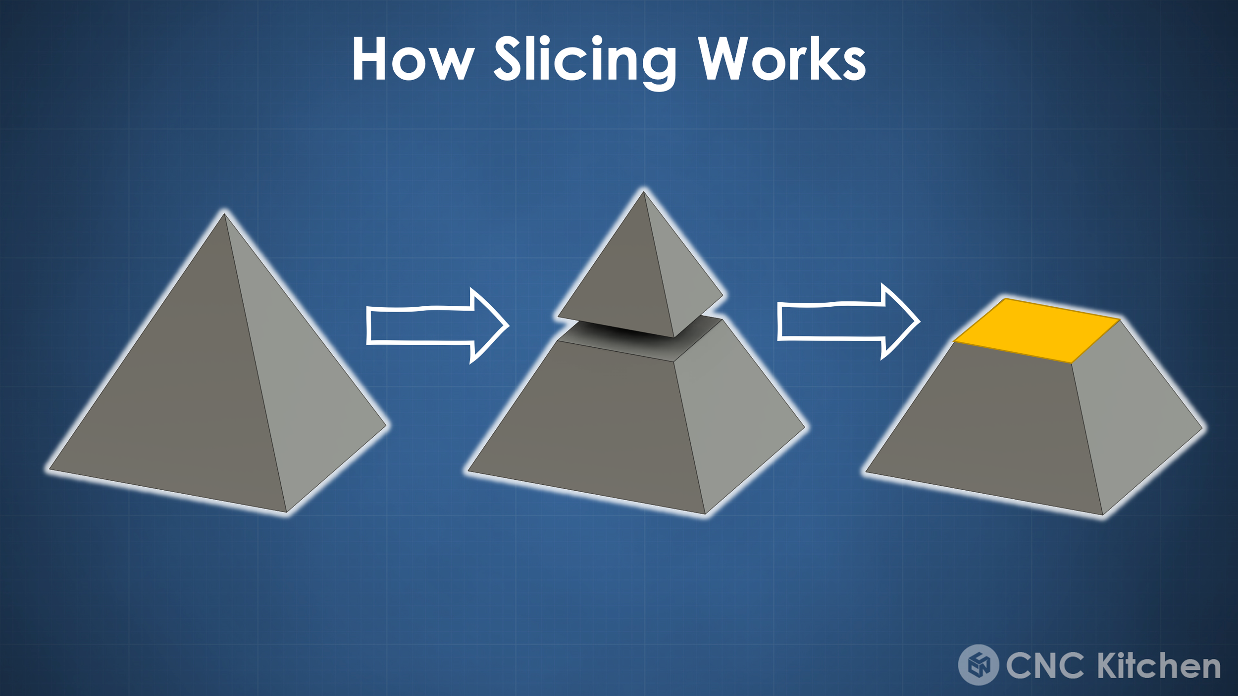
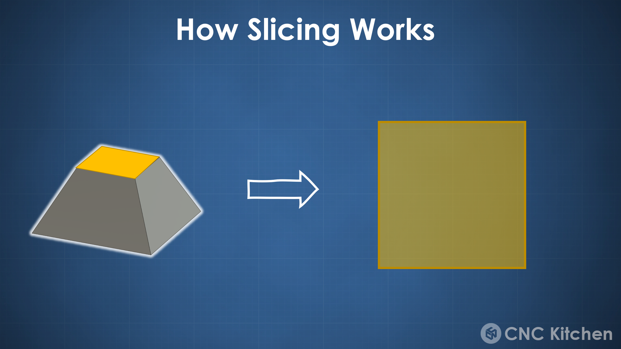
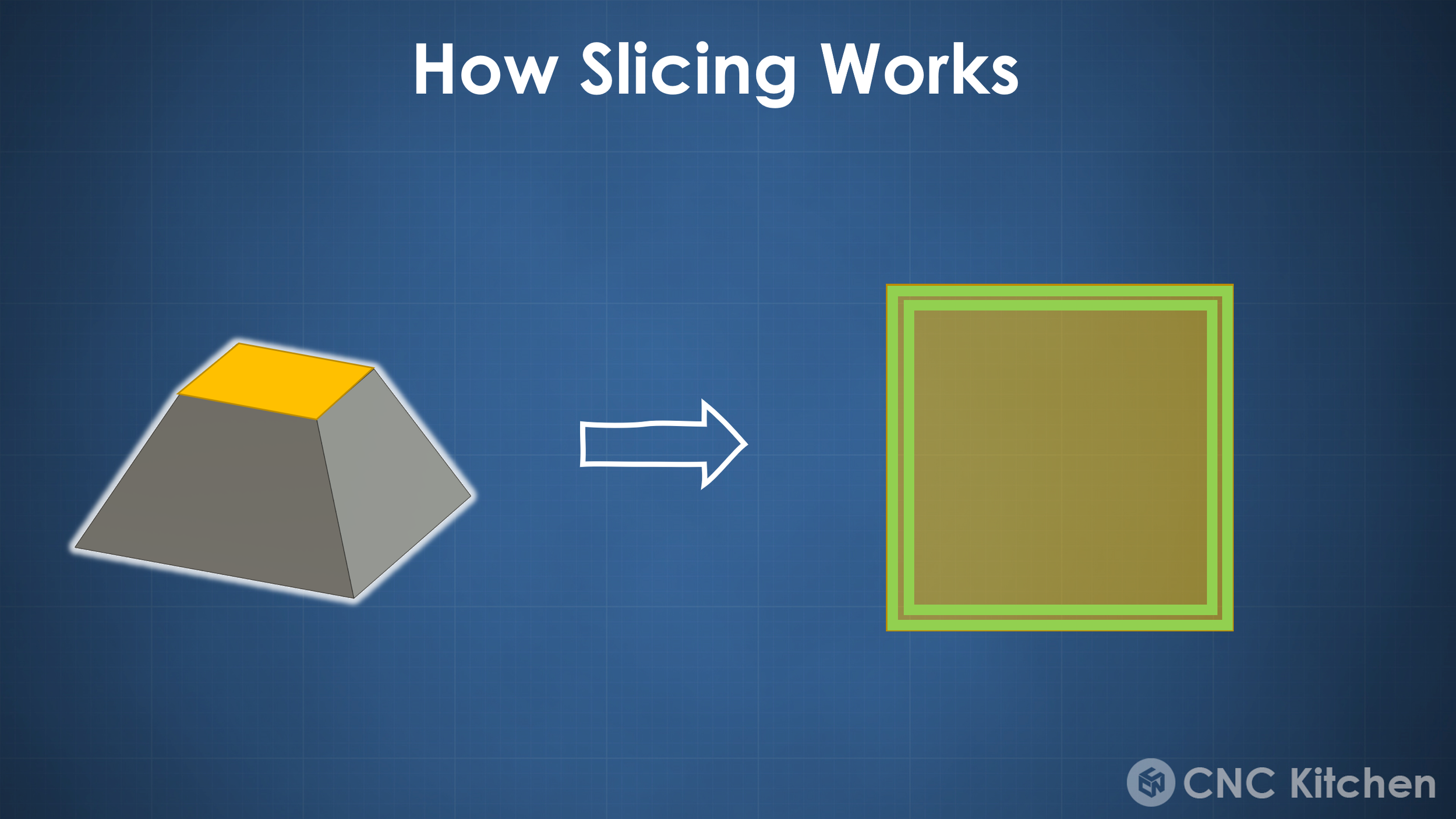
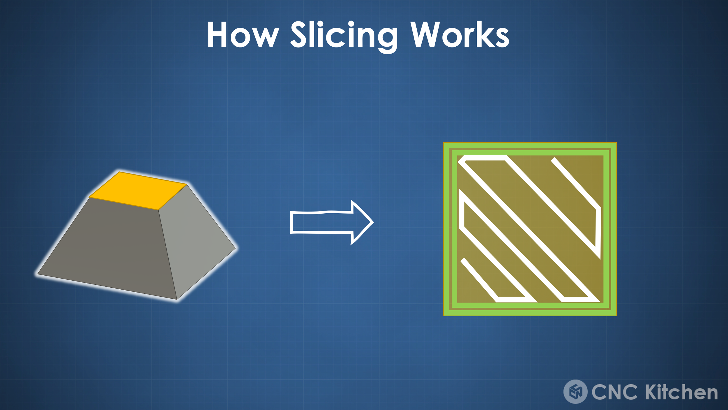
Current 3D printing slicers are dumb. What I mean by this is that even though they are slicers for 3D printing they simply stack 2-dimensional layers on top of each other to form your final part. There are basically no movements within the GCode instructions where all 3 axes move simultaneously. That’s why current 3D printing slicers are rather 2.5D slicers. But why are they using this approach? Well, simply because it’s mathematically easy and honestly because this approach works remarkably well. Yet we are leaving a ton of potential on the table because 3D printers are easily capable of complex 3-dimensional moves, yet we don’t have any software to take advantage of it. Over the last few years 3D printer slicers didn’t really change a lot besides being way easier to use and much quicker. Yet the general slicing approach always stayed the same. Cut a 3D part into a 2-dimensional slice, draw perimeters around the circumference and fill the rest with one of many infill patterns. The only real evolution we’ve seen this year is the Arachne Perimeter generator first seen in CURA that dynamically adjusts the width of the extrusions for more details and fewer gaps. Still, everything is on a two-dimensional plane, which causes the typical stairstepping pattern on sloped surfaces and of course, requires supports on overhanging structures.
Over the years we have seen a couple of approaches of non-planar slicing, often to improve top surfaces, yet none of them ever really made it into a mainstream slicer. Though quite recently we have seen a couple of really impressive ways of 3D printing parts that have previously been deemed impossible by using really clever slicing approaches. One of them is non-planar, conical slicing. A bunch of weeks ago I’ve shown this technique in my RotBot video, where I visited the University of Applied Science in Winterthur, Switzerland, where they built a 4-axis Prusa printer that can manufacture complete overhangs without the need for support structure. Yet the best thing is, that we can use the same slicing approach on regular 3-axis printers to achieve very similar results. And this isn’t just an idea published in a paper, but you can download the Python scripts necessary and try this out on your own parts and prints. I also uploaded a bunch of sample G-Codes on Printables for the not-so-programming-savvy! If you print them or even slice your own, please share the results and spread awareness around this method!
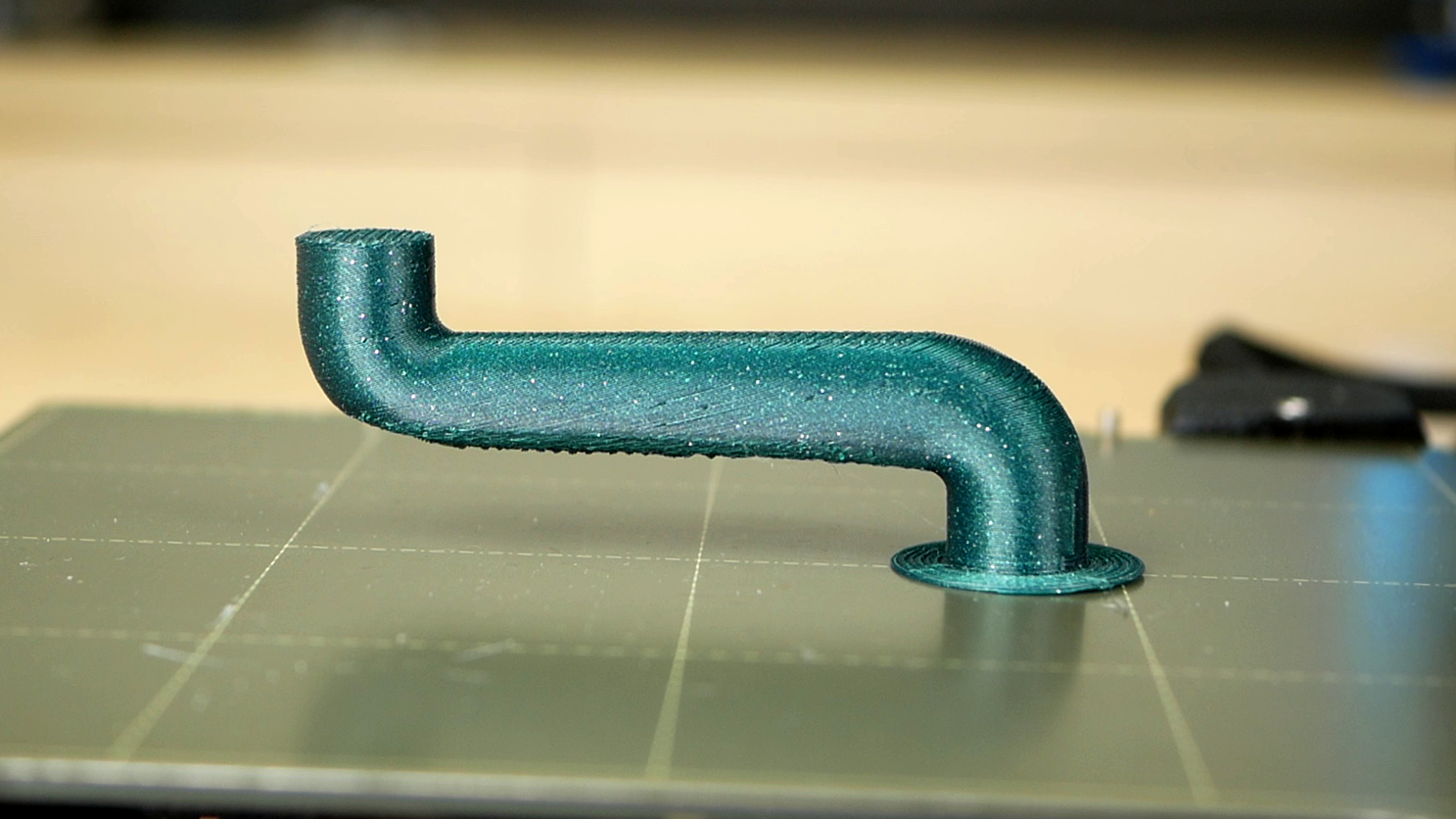
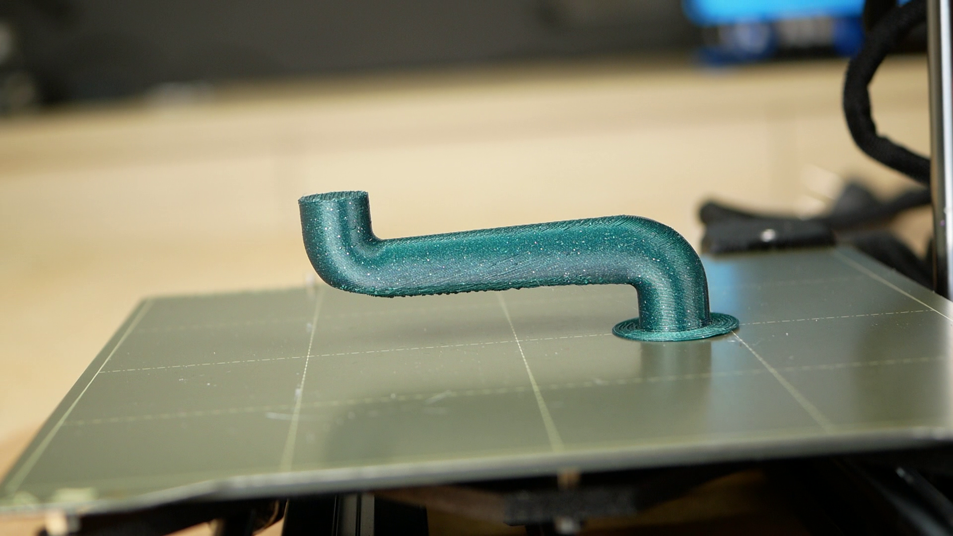
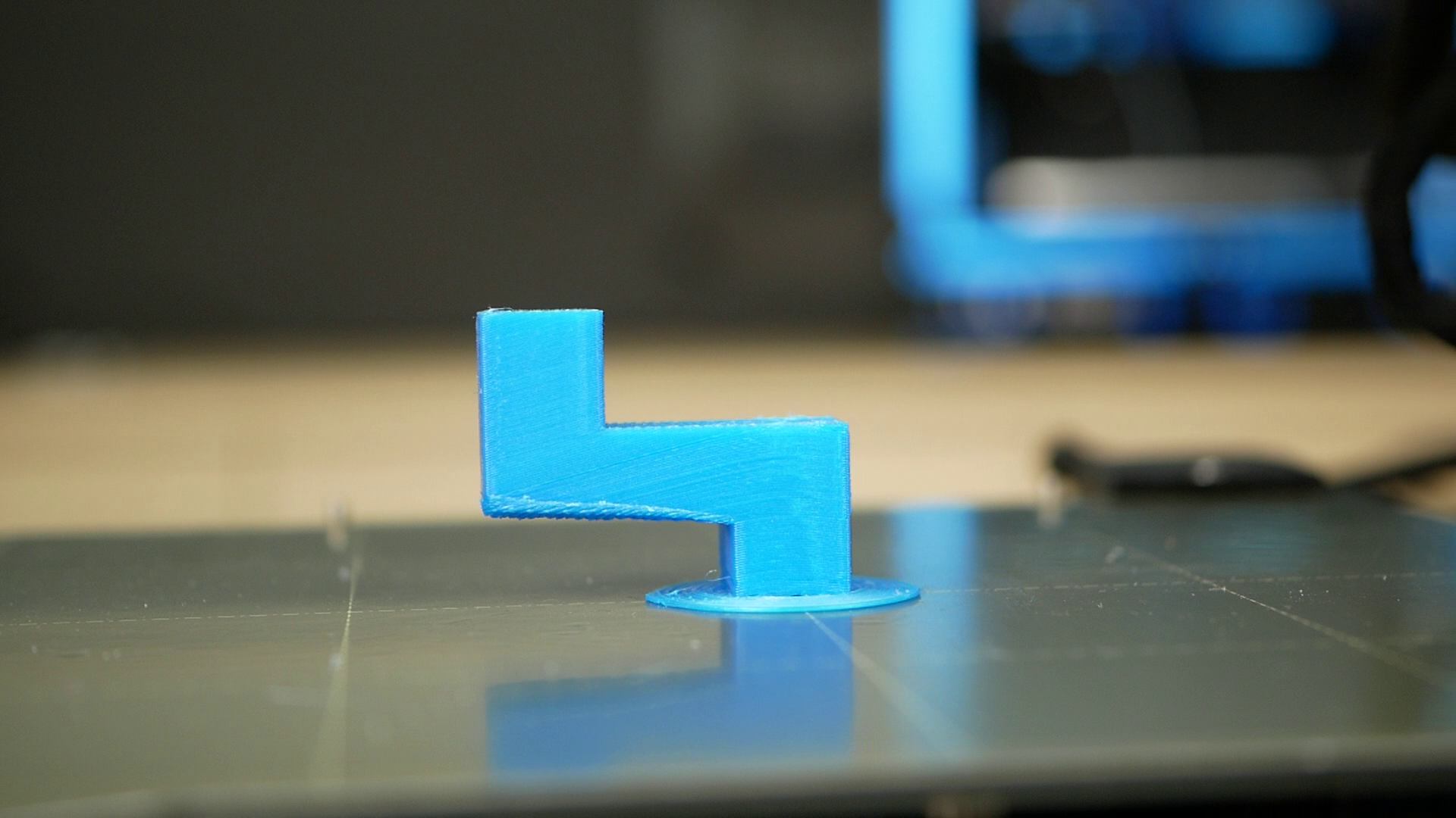
Supportless Pipe (Conical Slicing)

RotBot of the ZHAW Winterthur, Switzerland
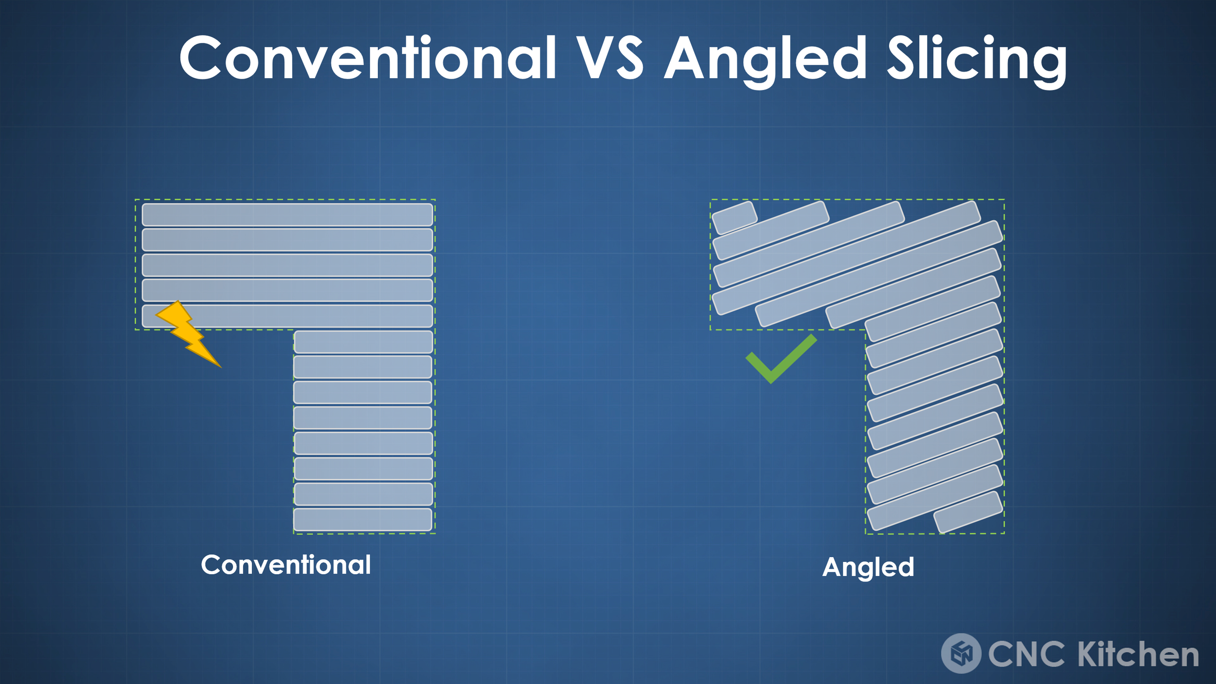
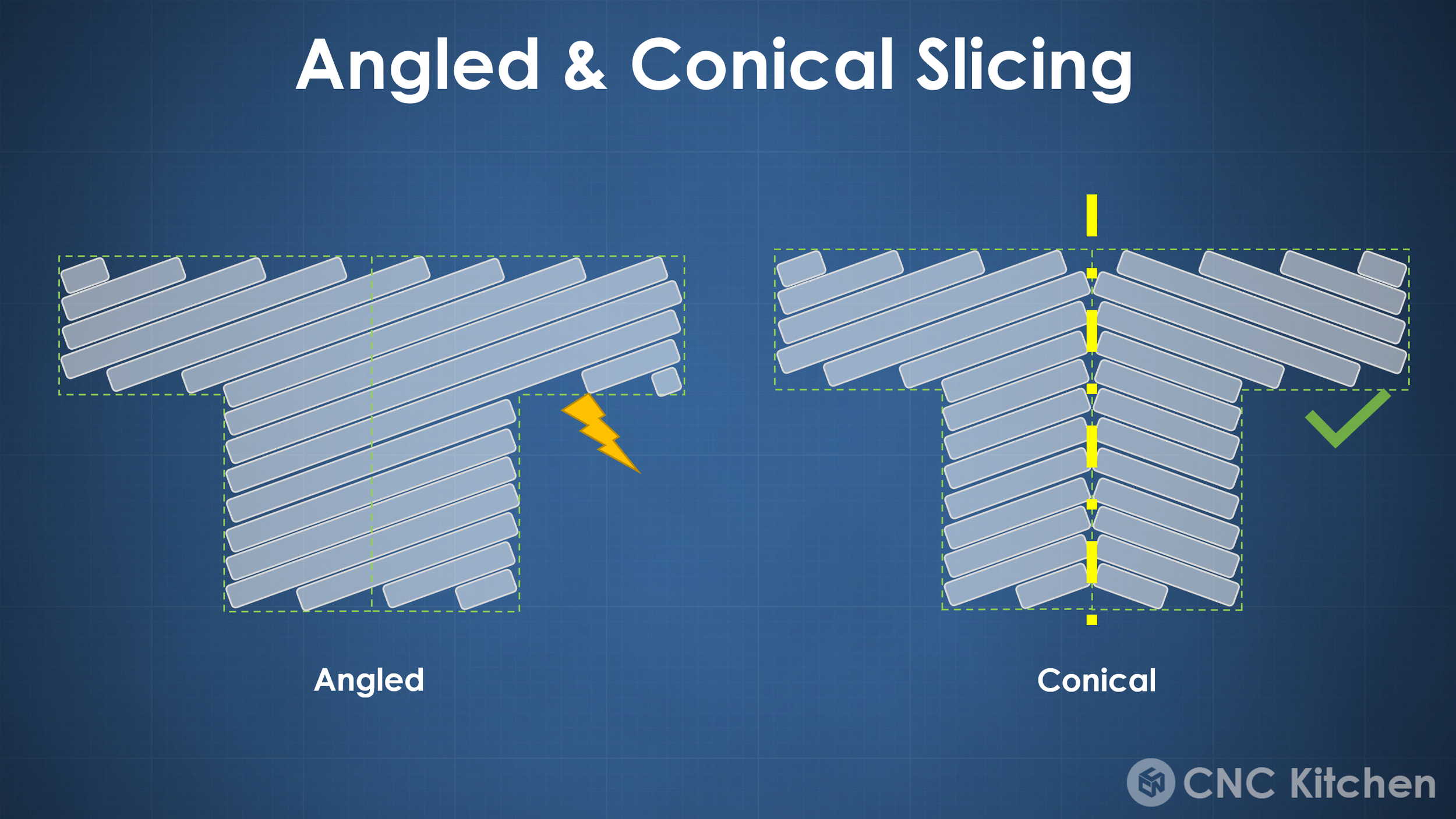
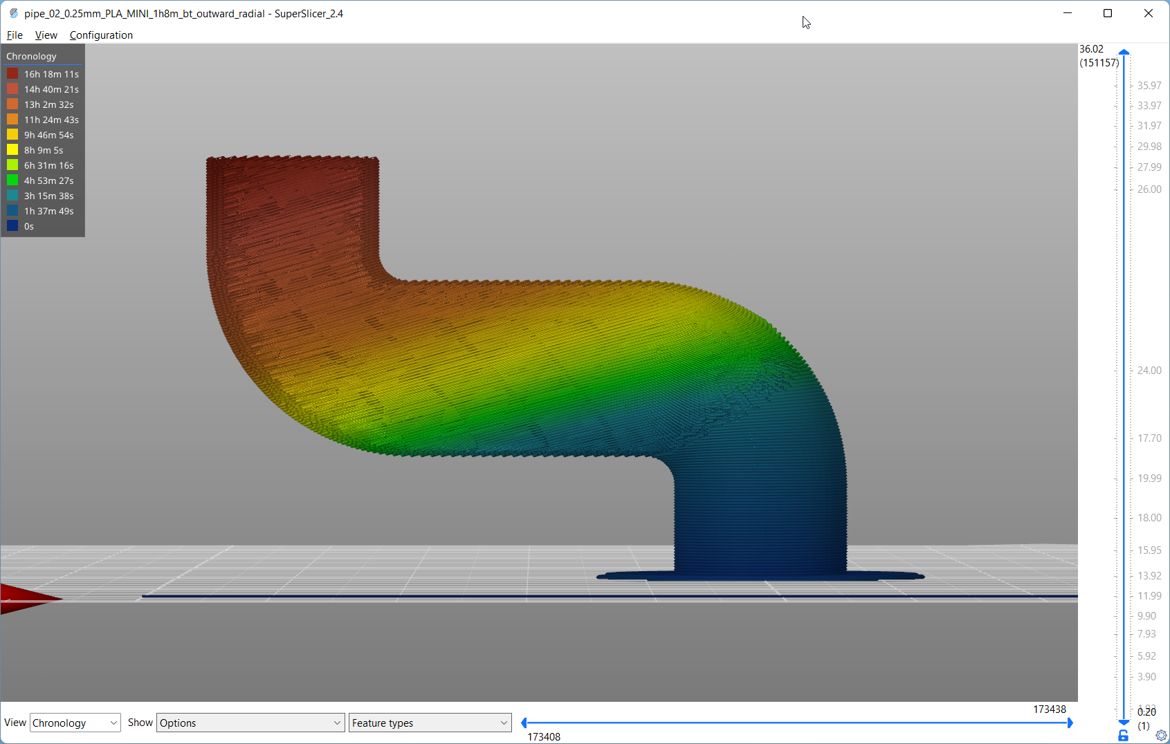
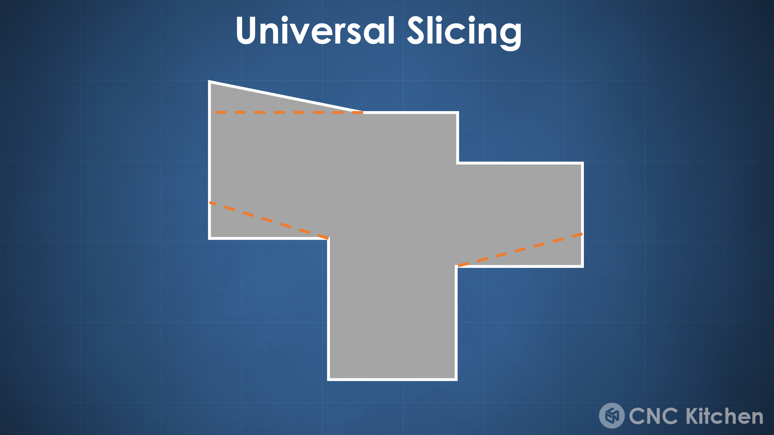
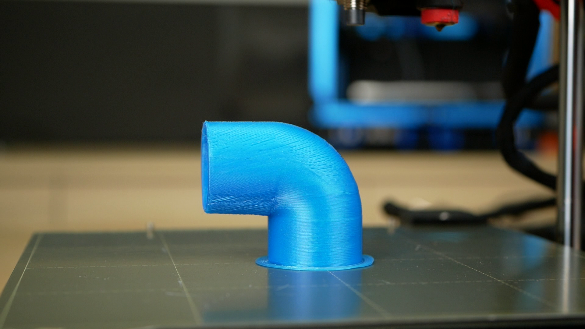
So let’s quickly talk about the idea behind this approach. Common FDM 3D printers are able to print quite steep angles, yet at some point, particularly below 10 or 15 degrees, the plastic will just be extruded into free air, drooping down and ruining your print quality. This novel slicing approach tilts the layers a tiny bit so that even when printing horizontal overhangs, only maybe the outermost perimeter is printed in mid-air, yet still sticks and is supported by the perimeter next to it. This way you can print even these extreme geometries without the need for supports. The conical slicing approach, which stems from the RotBot project, even improves this concept and tilts the printing layers around a central axis and therefore forms a cone.
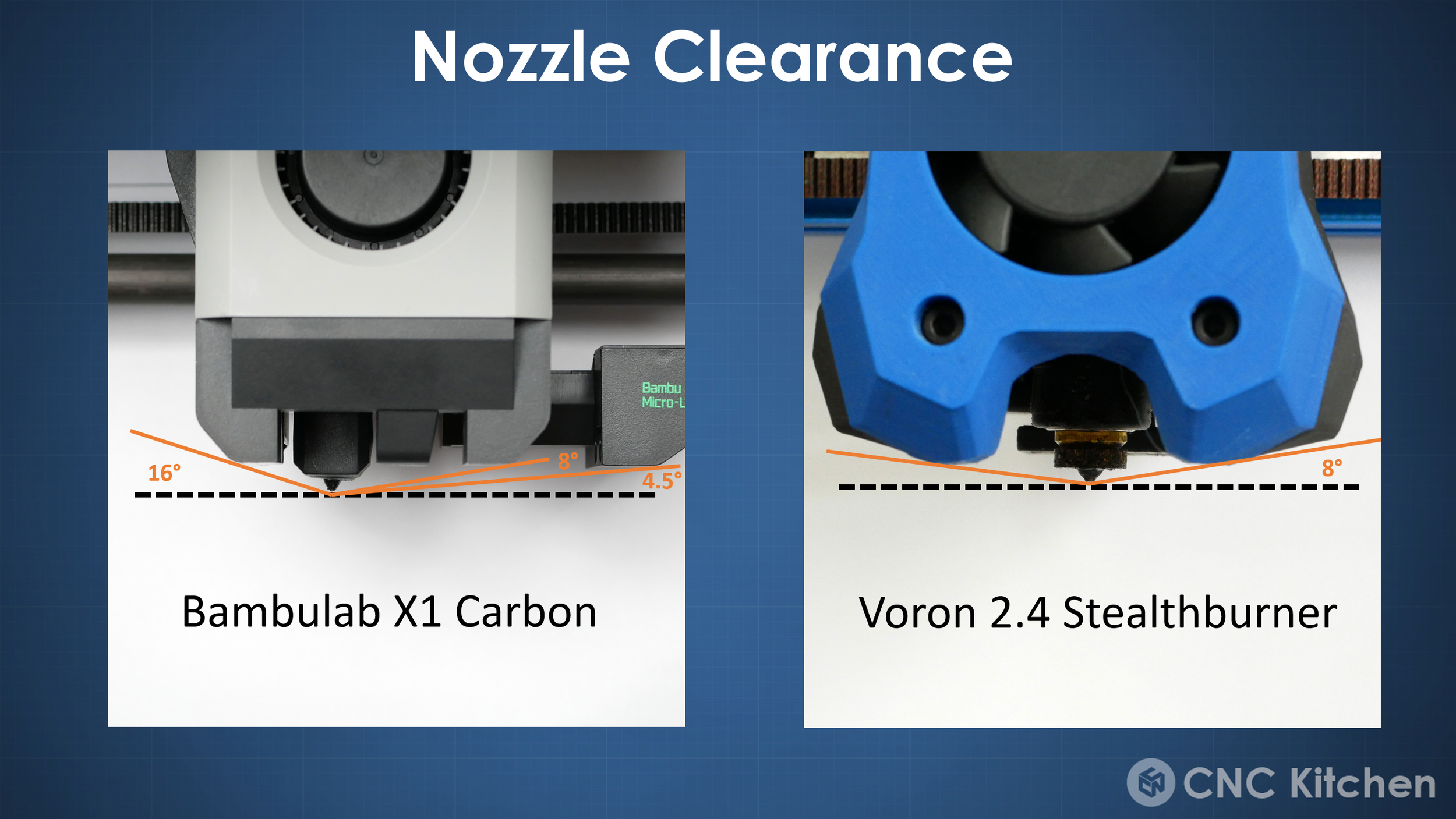
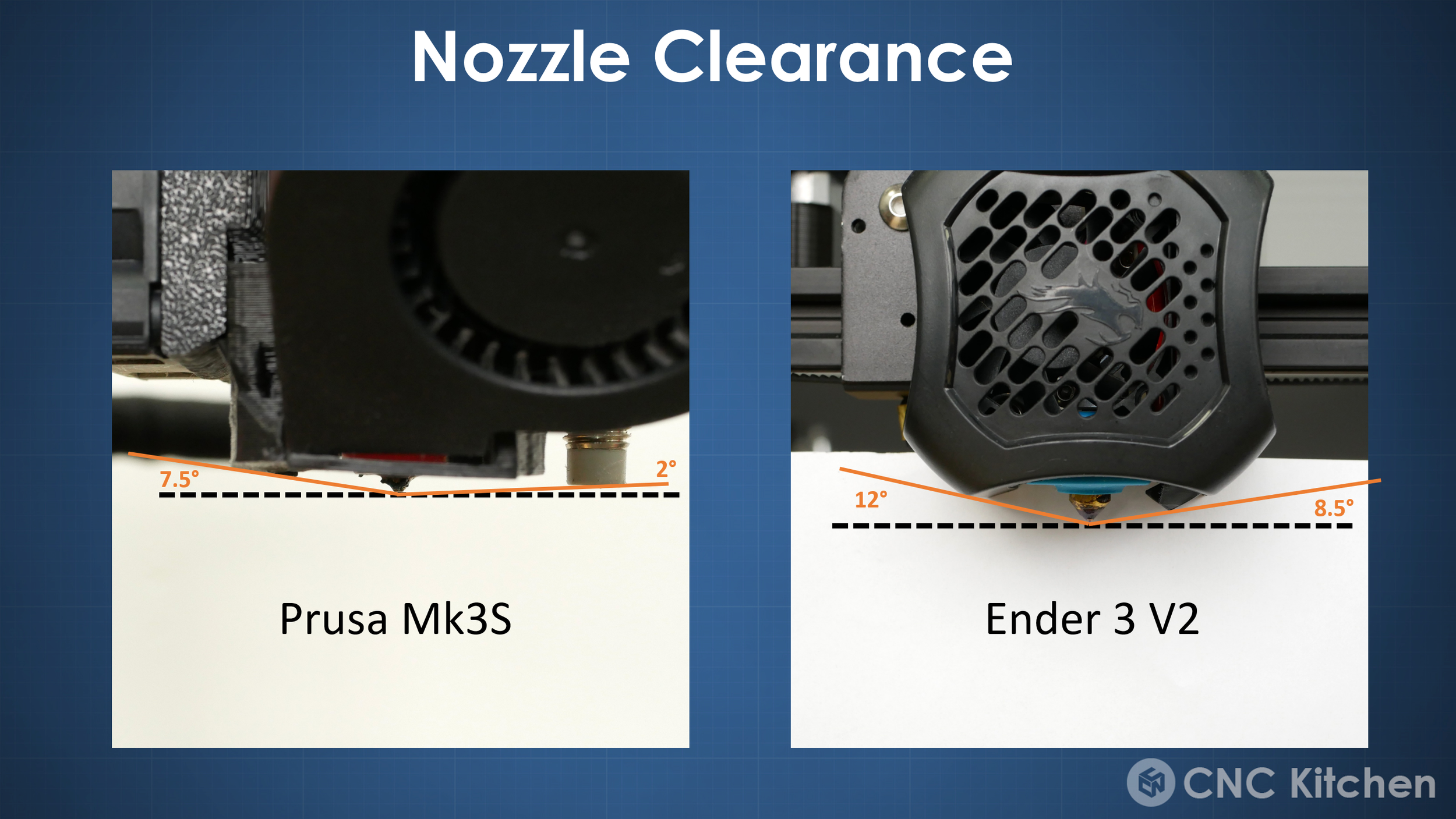
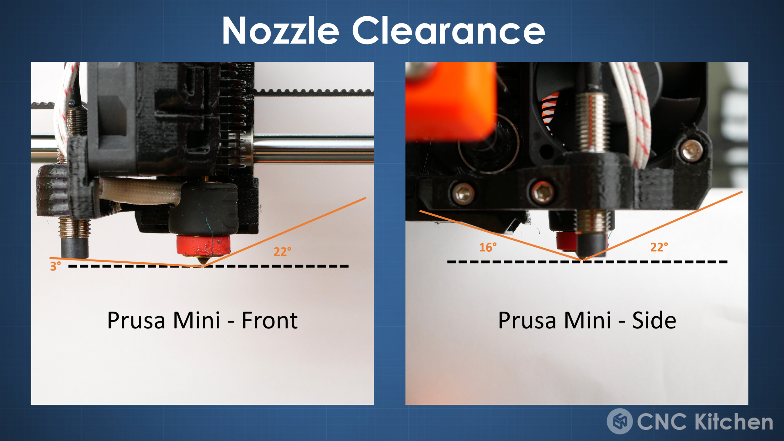
Since we’ll be printing our parts on a regular printer instead of one with a tilted printhead there is one essential thing that needs to be taken care of, and one of them is nozzle clearance. Conventional 2.5D printing only needs to make sure that the nozzle is the lowest part of the printhead, because we're only printing on a plane and nothing besides warped plastic should stick up. When we’re printing with non-planar GCode there are sections of the print that will be on a higher level than the current print move. This is why before we start the first non-planar code we need to figure out, what the maximum slope angle of our print can be. Unfortunately many current printers only allow tiny slope angles because of their cooling systems that reach down almost to the print plate. The only printer I had that worked acceptably out of the box was my Prusa Mini, which has quite a high part cooling shroud and if you print small parts allows up to around 20° slicing angle. Bigger parts will still crash into the bed leveling probe, and I often just pushed it up after the leveling process. For other machines like all the Ender-3 derivatives, a really simple solution is just using a longer nozzle, like one of these airbrush nozzles to which I put a link down in the description, or simply a regular volcano nozzle.

Artillery Hornet with Airbrush Nozzle
That looks a bit wired but works better than one might expect. Just remember to move your endstop! Unfortunately, cooling is not the best this way even though it’s quite essential for printing these extreme overhangs. The airbrush nozzle is a bit better here because it’s only a little longer than a standard nozzle and therefore still closer to the initial cooling location. So if you want to try this out make sure you have enough clearance and optimize cooling as much as you can!
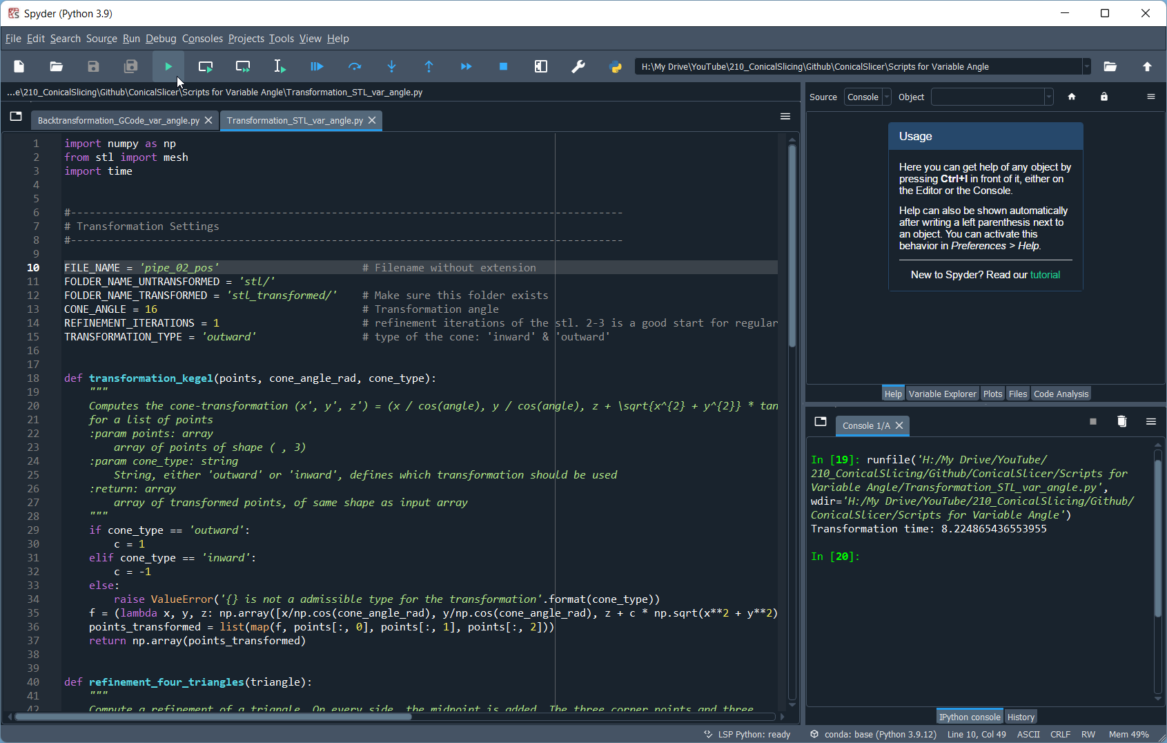
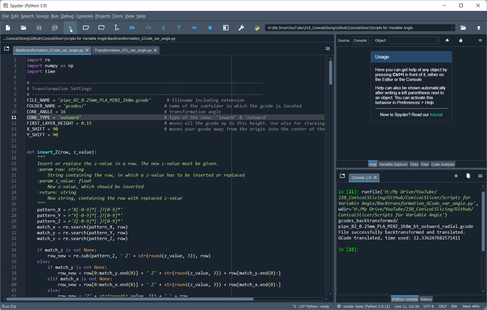
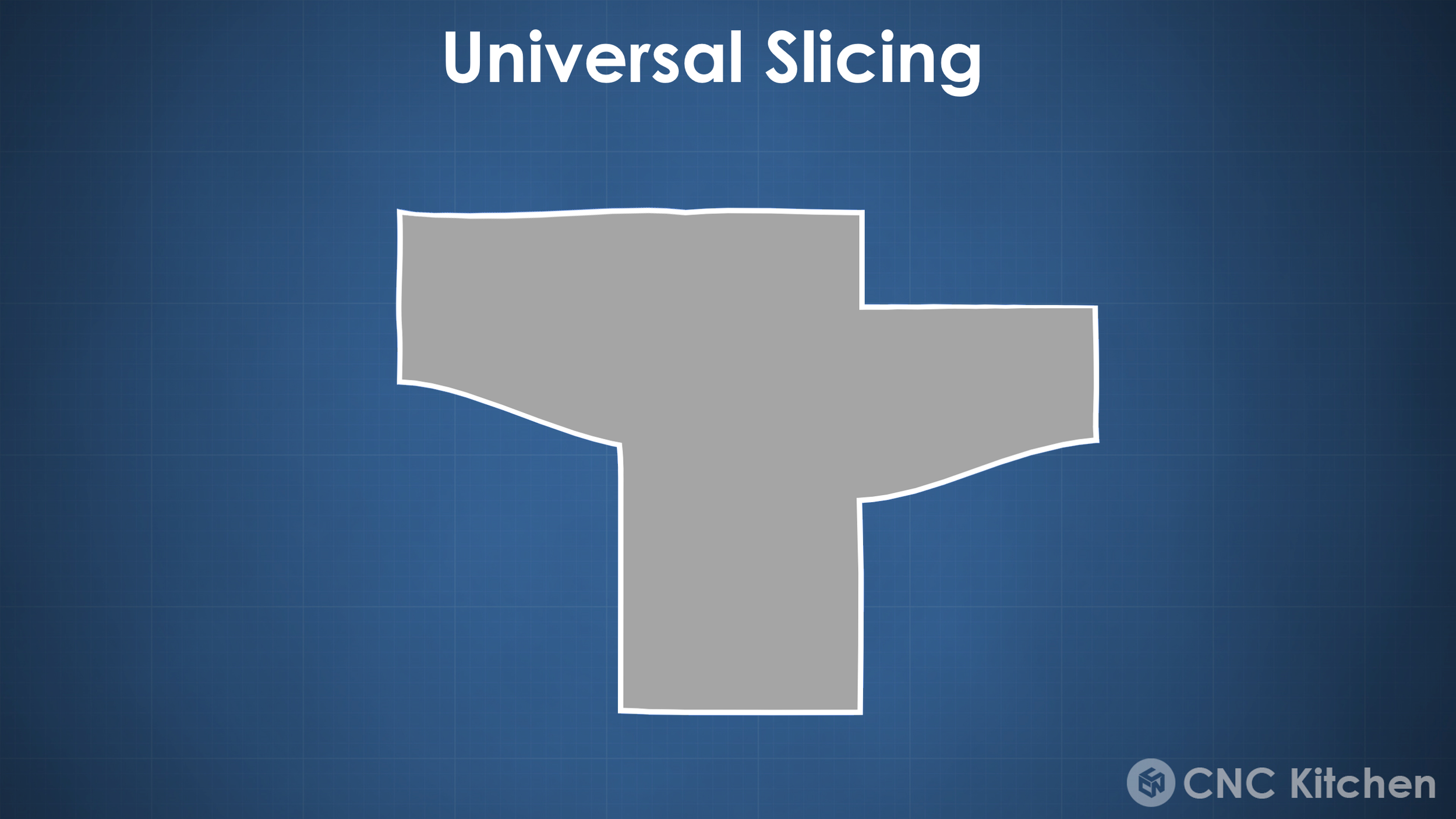
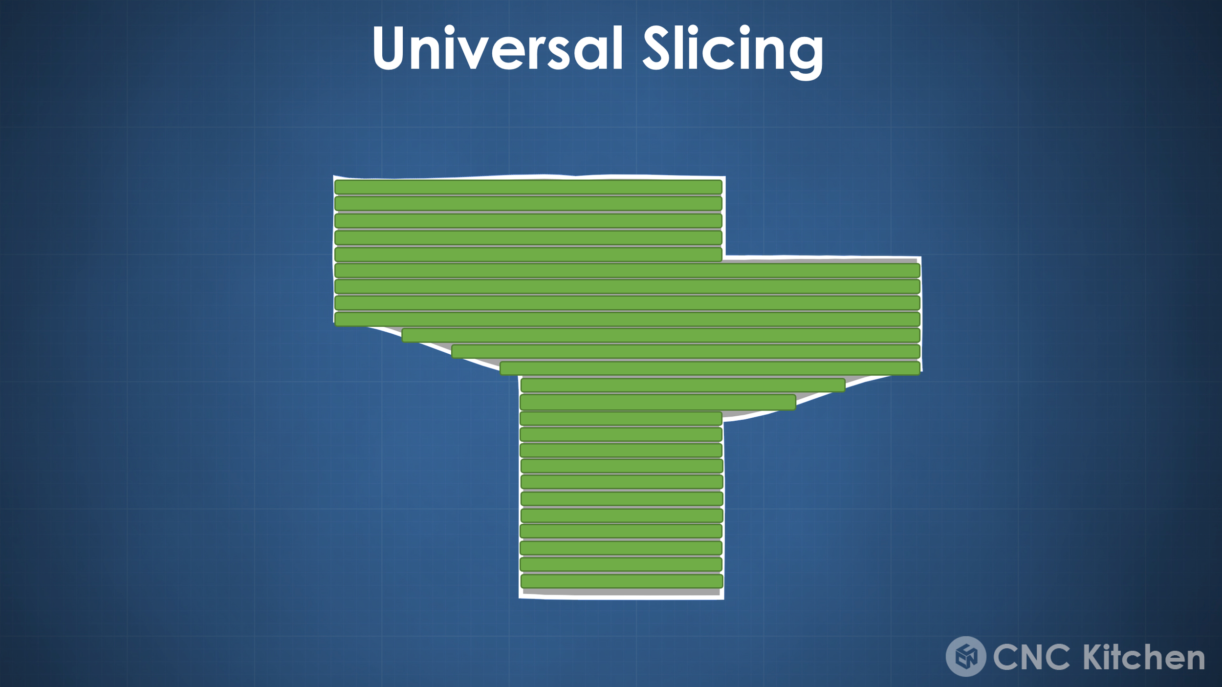
But which slicer can you use to create this tilted GCode? This is the cool thing about this method because you can basically use your own, favorite slicer for this. The thing is that there is no simple check box for conical slicing at the moment and you need to trick your slicer into generating conical GCode with a clever trick! We simply use two Python scripts for this, and I’ll go over how you can easily do this yourself in a second. The first code is pre-deforming the stl in a reverse cone shape, by simply moving the points of the mesh upwards, depending on their distance to the center axis. Then you slice this slightly wired-looking part in CURA, PrusaSlicer, Simplify3D or almost any other tool and use a second script to back-transform the movement commands within the GCode file to end up with the conical Gcode that’s ready to print. It’s really simple!

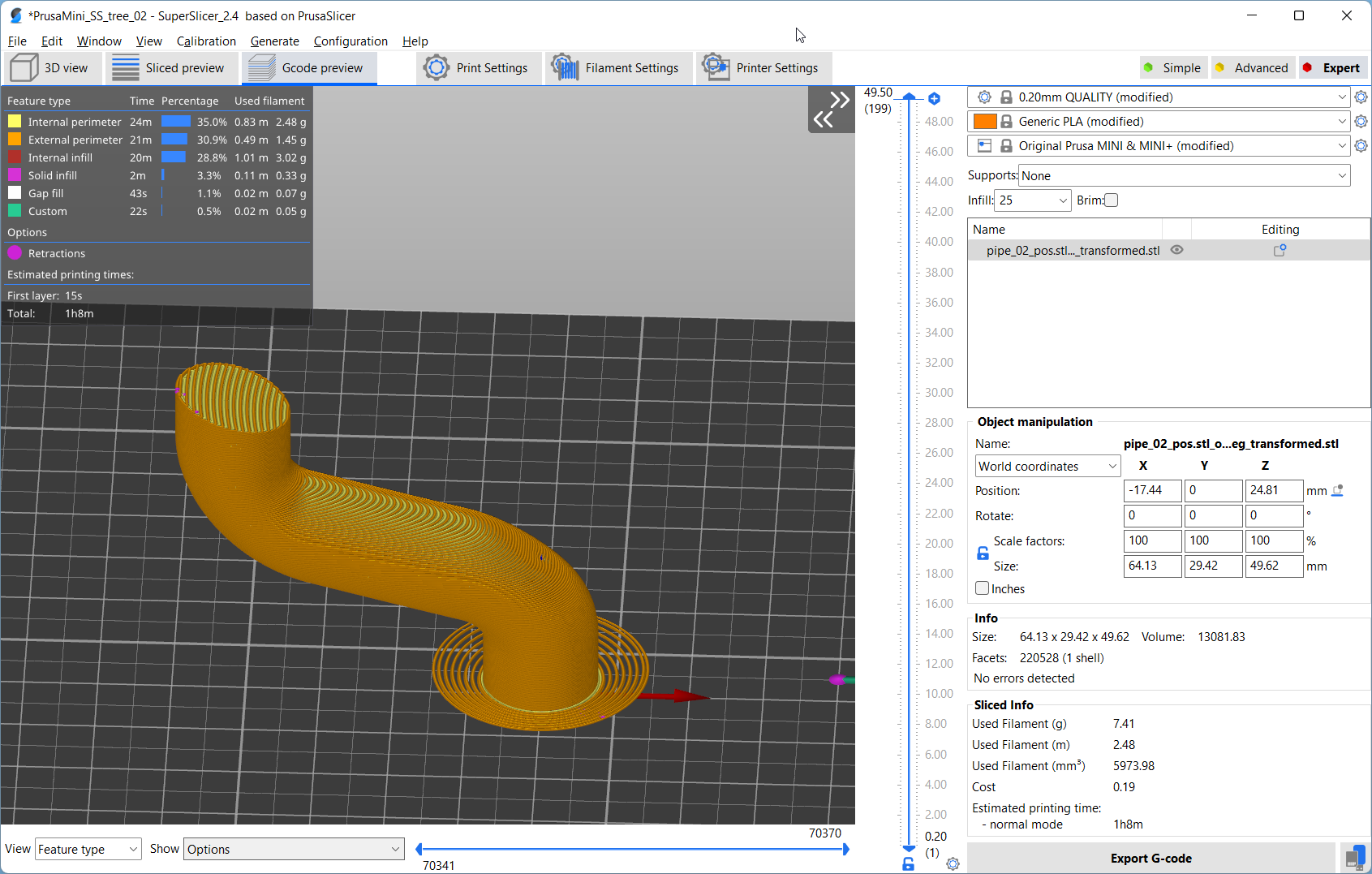
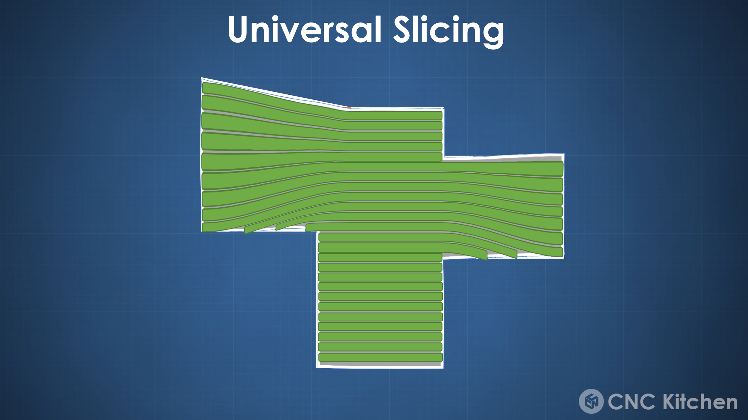
Conical G-Code preview
If you want to try this out yourself all of this is Open Source, and was developed by the ZHAW in Switzerland. During making this video and working with their code I created a fork of their project to make it in its current state easier usable, fix some bugs and add some features. Nothing really crazy but in my opinion, it works better.
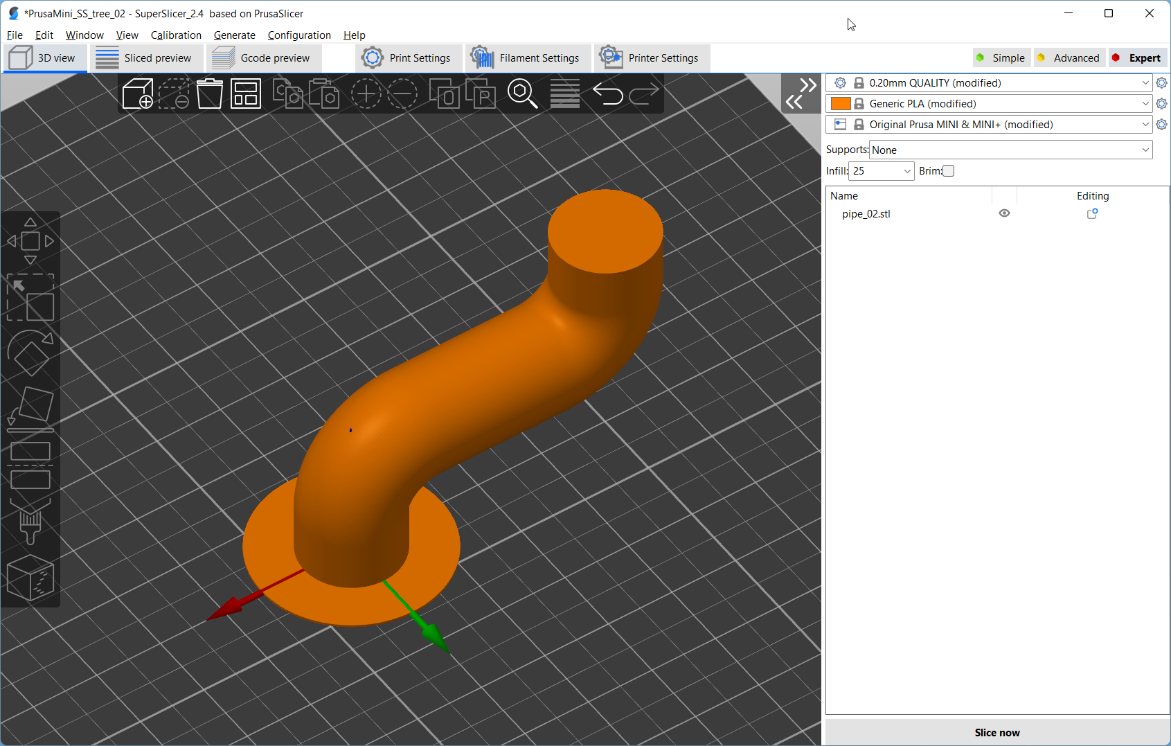
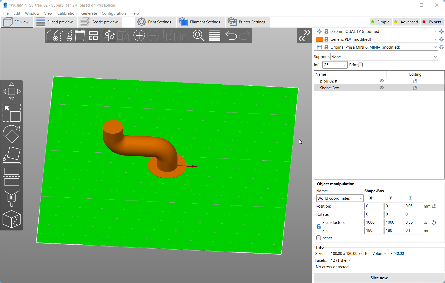
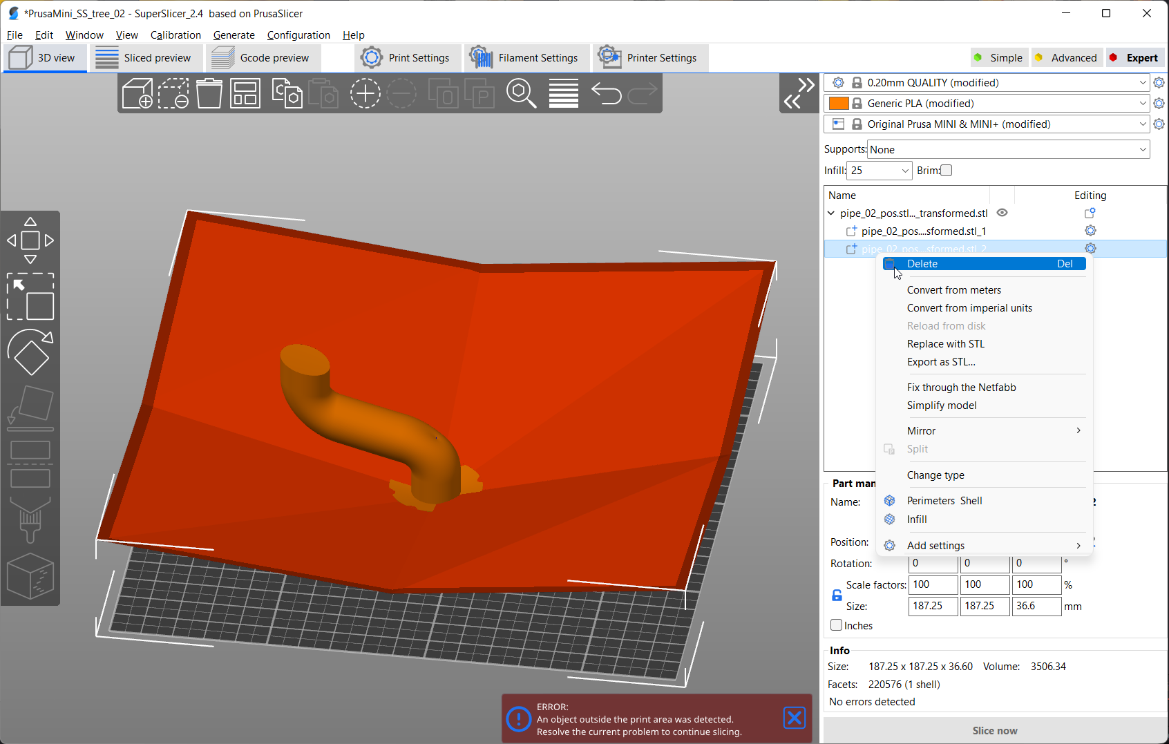
So here’s the process and I’m using SuperSlicer for this demo because it has some additional features over PrusaSlicer and most importantly has a switch that lets you export GCode with empty layers, which is sometimes really handy for this method! I load my stl file into the slicer with a slightly adjusted printer profile where the bed origin is in the center. I move my part so that the global z-axis represents the axis of the cone that I want to use for slicing and save the part in this new location. In the transformation script, I set my slicing angle and run it which spits out the pre-deformed stl, that’s ready to be loaded back into the slicer. Now I make sure that the cone axis of the slt is again at the origin of the coordinate system and then simply slice my part and save the GCode. Then I paste the name of this GCode into the second script, make sure that the right cone angle is set, and hit run to start the back deformation. And that’s it! Ready to run conical GCode generated in a minute! I also wrote a comprehensive guide on my website through which you should go step by step to ensure that you get out nice GCode because some essential things need to be taken care of! One of the huge pain points of PrusaSlicer and CURA is, that they don’t position parts in their local STL coordinate system but choose one by themselves. There is a switch in PrusaSlicer that should get around this, but it seems to have been broken for a while, so please guys, fix that because currently, I need to use a ton of trickery to position non-symmetric parts properly.
The approach is not perfect, still buggy, and requires a bit of manual work but demonstrates how this novel slicing technique could be implemented in a regular slicer. Yet, conical slicing won’t fix all of our overhang and support problems at the moment. If you have watched carefully, you will have noticed that most geometries I’ve shown so far only had outward-facing overhangs. Any inward-facing overhangs actually would need even more supports as with the regular 2.5D slicing approach. The current script also allows slicing parts with an inward cone, yet if your part has both outward and inward-facing overhangs you will need to slice the sections separately and stack the GCode manually. If you have both inward and outward-facing overhangs on the same height, you won’t be able to find a solution at all! And this is one of the main limitations of conical slicing in its current state. It works great for special geometries, but will probably not be as impressive for any arbitrary geometry. What we’ll need in the future are algorithms that automatically section the parts, depending on their geometry, and set individual slicing angles and orientations. An implementation I could imagine for the future is identifying geometries by their overhang angle or slope angle and calculating an ideal slicing angle for supportless overhangs and smooth top surfaces. In-between you can interpolate. This field could then be used to pre-deform the stl and also used for back-transformation giving us non-planar G-Code even with variable layer height. I’m not the first to come up with such an idea, and you can find plenty of papers on approaches and algorithms.

Unfortunately, I don’t have the time and probably the skill to do this myself, but I want to spread awareness of how much potential there still is in slicing software for FDM printing. So if you’re a skilled enthusiast with too much spare time or a student looking for a thesis maybe consider if a proper non-planar slicing integration is the challenge you were always looking for. Anything that we as a community can release and contribute open-source is something no one else can patent. Yet if you are a software company, also think about if you’d like to be the first to do proper non-planar slicing with your tools. I was happy 6 years ago to pay for Simplify3D because it did the best supports at that time and I’d honestly be happy to pay a reasonable amount for a next-generation FDM slicer!

Yet new slicing methods, especially non-planar will also require adjustments in the hardware of our printers. This is why I think, that we won’t see this being implement in PrusaSlicer and CURA soon, because their machines, especially their printheads are not yet optimized for that method. Something you have already seen plenty of in this video is the clearance around the nozzle so that non-planar moves are even possible without crashing into the print. Also, how should the tip of the nozzle itself even look like, because the bigger the flat, the more it will interfere with the extruded plastic. Yet the smaller it is the less ironing action we will have and material will squish out to the sides. And then there is the z-axis. When this axis is involved in every print movement it will need to move way more than in a regular print and probably wear out quicker with the common leadscrew approach. And of course, cooling also plays a major role if we want to print supportless and need to cool down the plastic as fast as possible. So there is still a ton of really interesting research and development necessary until we see non-planar slicing in all of our prints, but I think we have finally reached a point where proper implementations are really close! I’d love to hear your thoughts on the conical method and non-planar slicing in general. Do you think the current 2.5D slicing approach is just good enough or do you also see this huge potential in new algorithms? Please let me know in the comments below!