The RotBot: 4-Axis Non-Planar 3D Printing
“Complexity is free” is a sentence that’s often used for marketing 3D printers and 3D printing technologies. Even though up to a certain degree, this is true, depending on the additive manufacturing technology that you’re using, there are still geometrical limitations that a designer needs to take into account. Filament-based 3D printers can print very complex structures, but when it comes to overhangs, there is just a physical limit that can be achieved with conventional machines and current slicers. Unsupported overhangs will simply start drooping down at a certain point, leaving a very bad surface finish, resulting in geometrical deviation and can even cause print failures. You can use support structures, but they require printing time, can be hard to remove and simply cause waste.
A couple of weeks ago I was invited to the ZHAW the Zürcher Hochschule für Angewandte Wissenschaften, a University of Applied Science in Winterthur, Switzerland in order to take a look at one of their projects, the RotBot. The RotBot is a modified Prusa MK3, with a DUET control board, but, more importantly, a fully rotatable 45° tilted tool head that doesn’t only look super mesmerizing when it prints but it’s also able to print completely overhanging structures without any support.
I was greeted by Michael Wüthrich, who is one of the lecturers at the University and who built the RotBot with his team. One of the reasons why I decided to take a look at the machine is not only because it shows how awesome real multi-axis printing can look and what you can achieve with it, but also because the design files for the tool head, as well as the scripts used for slicing, are fully open source. So if you’re interested in the technology, take a look at the links in the description.

The RotBot printing a part
When I visited their printing lab, which honestly made me kind of envious, I also saw, that the RotBot wasn’t their first attempt at multi-axis 3D printing because already Michael's predecessor, Professor Elspass and his team, had already built a complex 6-axis delta printer called the MaxBot for similar endeavors. Yet fortunately, the RotBot is significantly simpler and should be adaptable to a wide range of other printers. The core of the RotBot is its rotatable printhead with the 45° nozzle. There is an E3D Hemera direct extruder on the top, which feeds the filament that’s guided through a stepper motor that has a hollow shaft down to a slip ring that enables all of the wires to not get tangled, allowing completely free rotation of the hotend and which also acts as an additional bearing. Then there is a slightly modified V6 heat sink and the 45° heater block and nozzle, which is basically the only real custom, non-printable part in this build. They went for a DUET control board, that’s easily configurable and does have the extra stepper motor driver for the 4th movement axis. To increase clearance, they had to get rid of the bed level sensor, that’s now used to home the rotation axis, and a simple microswitch homes z.

Section view of the RotBot toolhead
Yet, hardware is only one part, and in my opinion, the easy part in multi-axis non-planar 3D printing, and I’ve already discussed that several times. More than 3-axis CNCs are very common in manufacturing, and multi-axis robot arms are also more affordable than ever, but to my knowledge, there isn’t a ton of software available to create Gcode for 3D printing for these machines that’s also affordable for makers. This is, in my opinion, one of the reasons, why non-planar and or multi-axis printing hasn’t had its breakthrough. Slicing software and slicing methods are the challenge, not the hardware!
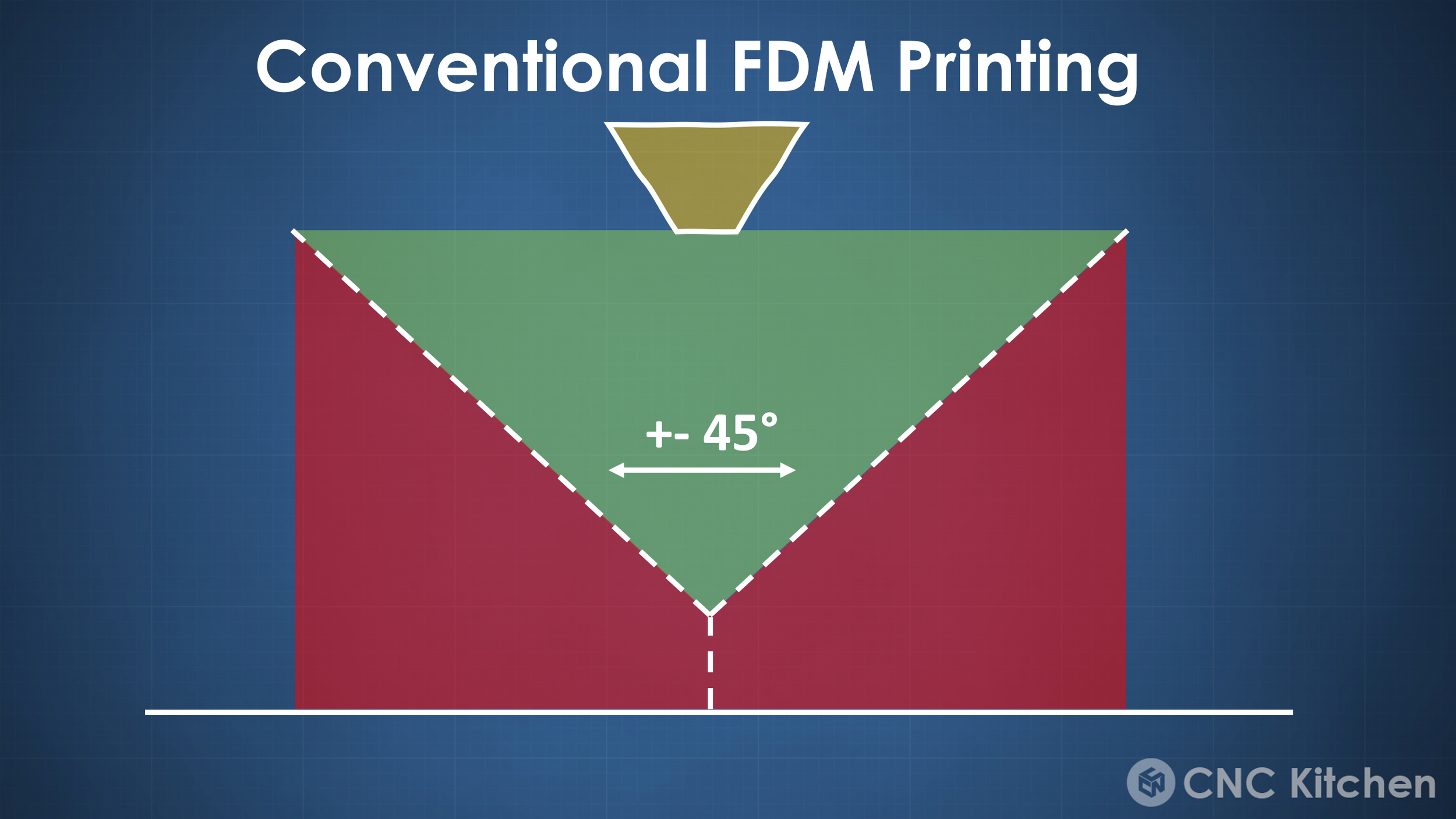
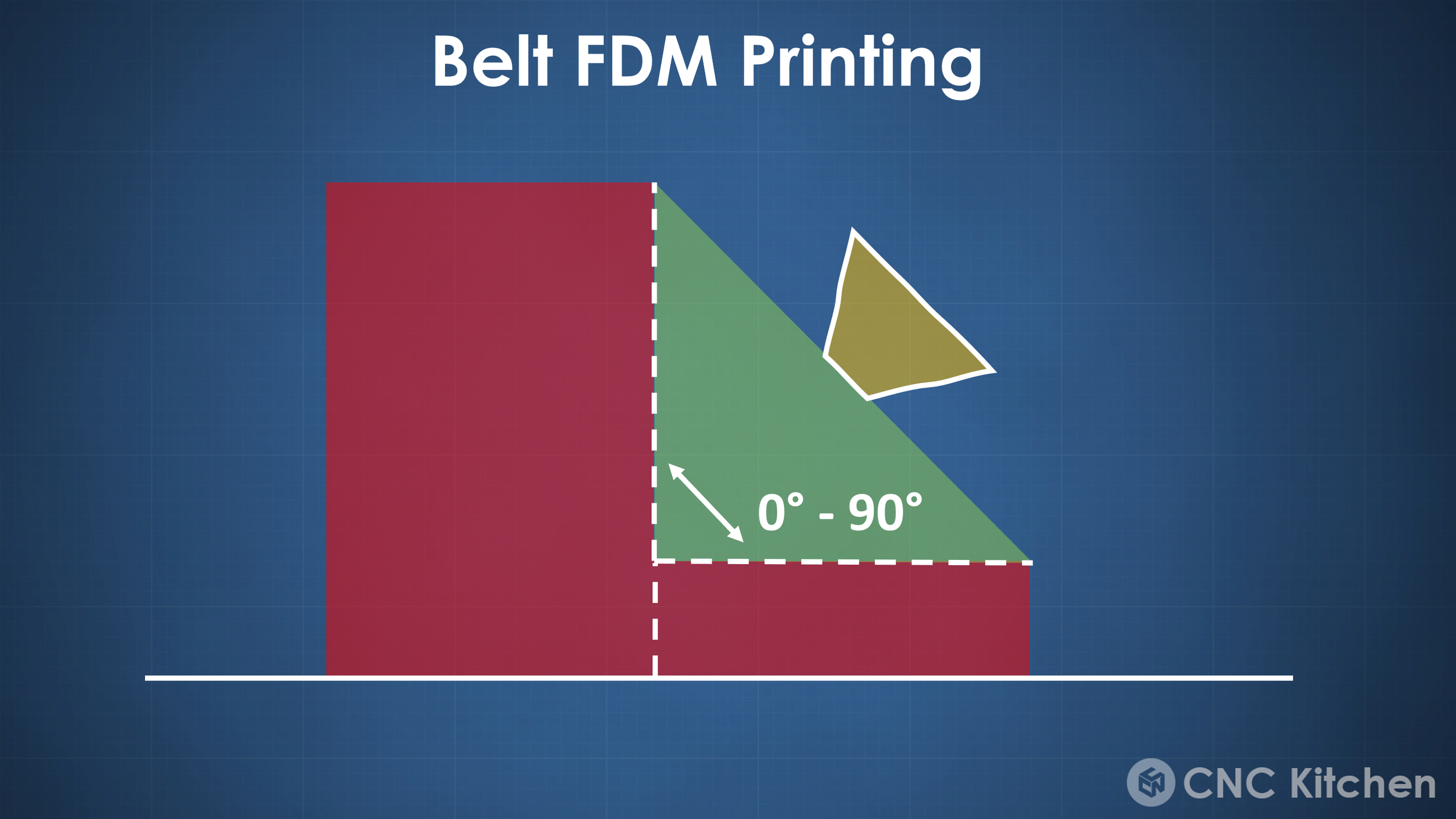
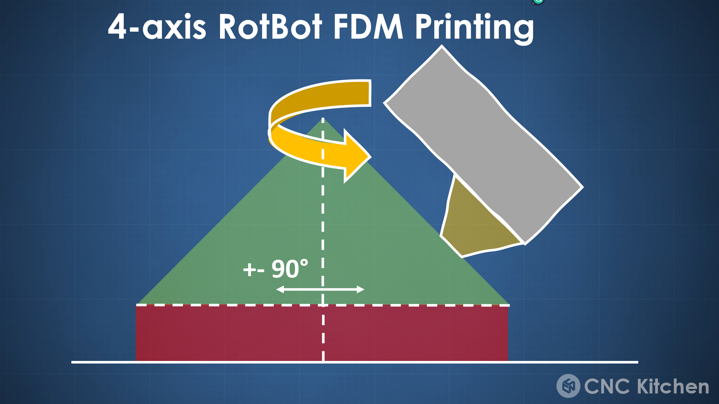
The slicing approach that Michael and his team developed is so simple, yet effective, that I hope to see more work on it in the future and hopefully have it in common slicing software at some point. Very generalized, with a common FDM 3D printing slicer, you can print overhangs in this +-45° window. Common belt printers, which have an angled nozzle, tilt that window to 0°-90°, and this is where the RotBot improves on. With its rotating printhead, it can reach all around a part and increase the window to around +-90°, which allows completely overhanging structures on all sides and without any supports and therefore generates cone-shaped layers - hence the name “conical slicing”.
Conical slicing is the method that’s used to generate the g-code for the printer, yet they didn’t program a whole new slicer but simply trick regular software into generating the paths and then modify that code with a bit of python script. I’ve heard of that method in the past, yet never really understood it until Michael explained it to me and the paper that’s also linked below illustrates the approach very well. We have three steps. Predeformation of the STL file, slicing that predeformed STL in a regular slicer, and back-transforming the G-Code. But let me try to walk you through this in more detail!

Conical GCode
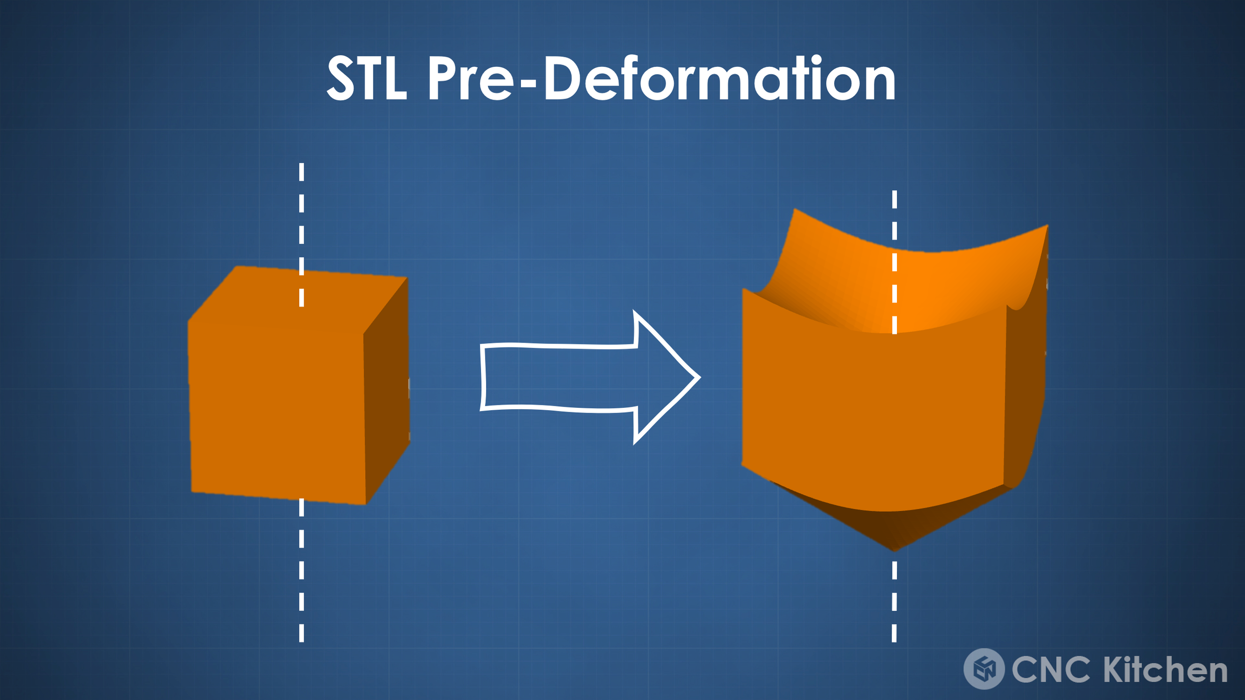
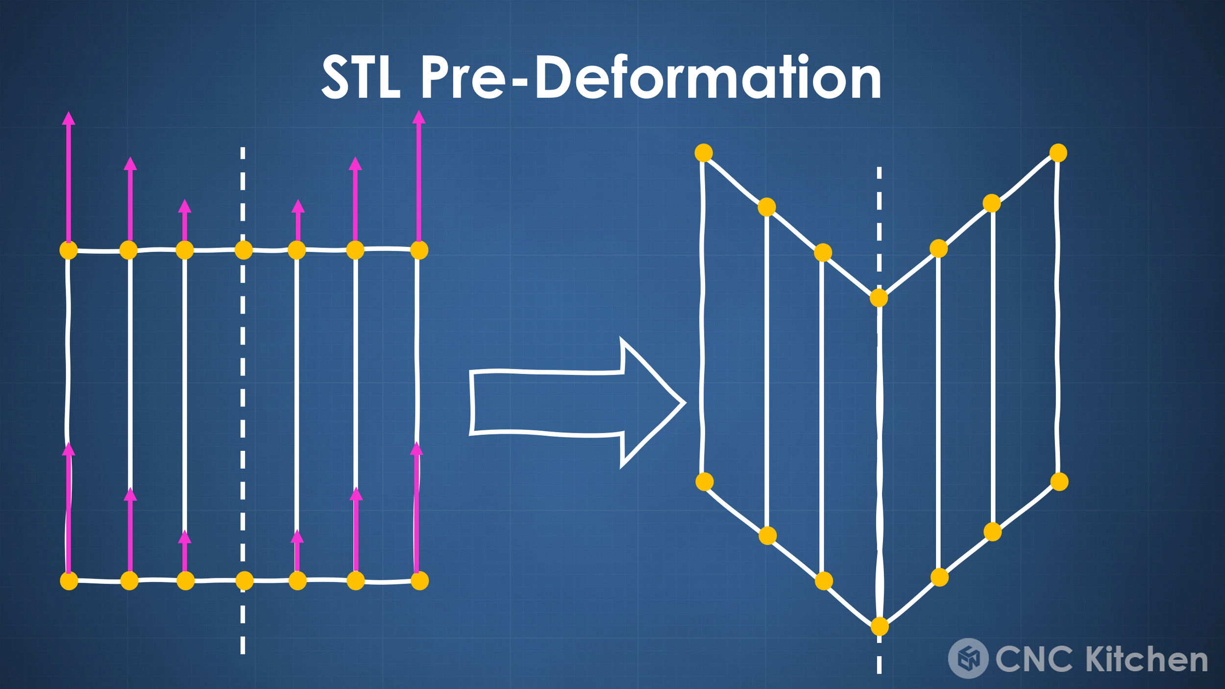
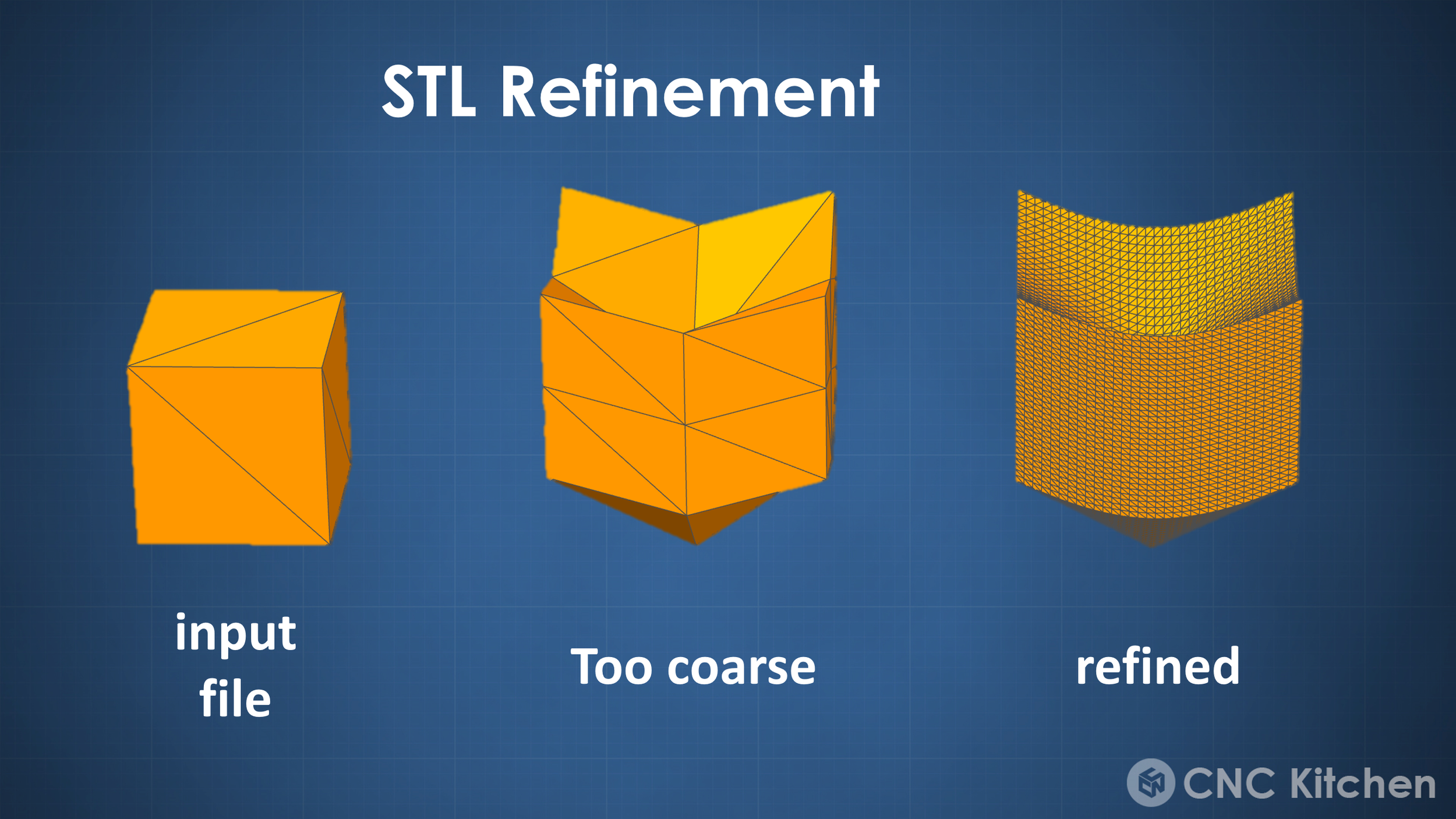
First, let’s talk about pre-deformation. This is done so that a regular slicer can later be tricked into generating the conical gcode. For this all the points of the mesh are moved upwards in z-direction, depending on their distance from the defined rotation axis. Since this can lead to serious artifacts depending on the mesh fineness of the part, the python script can also refine the mesh to make the final result smoother. This process leads to a conically deformed part at the 45° angle of the nozzle of the RotBot. The deformed part is then brought back into the slicer, and a regular Gcode is generated. I had to use Simplify3D with the current version of the script because it seems to use some comments injected by the slicer for the back deformation, but that’s something that’s probably easily fixed. This GCode of the deformed part then gets back transformed, so exactly the reverse process of what we did to the STL in the beginning. So all the GCode points are moved down again depending on their distance to the center axis. There are some edge cases that need to be considered, like longer linear moves, that would cause crashes with the already printed part or flow rates that need to be slightly adjusted.
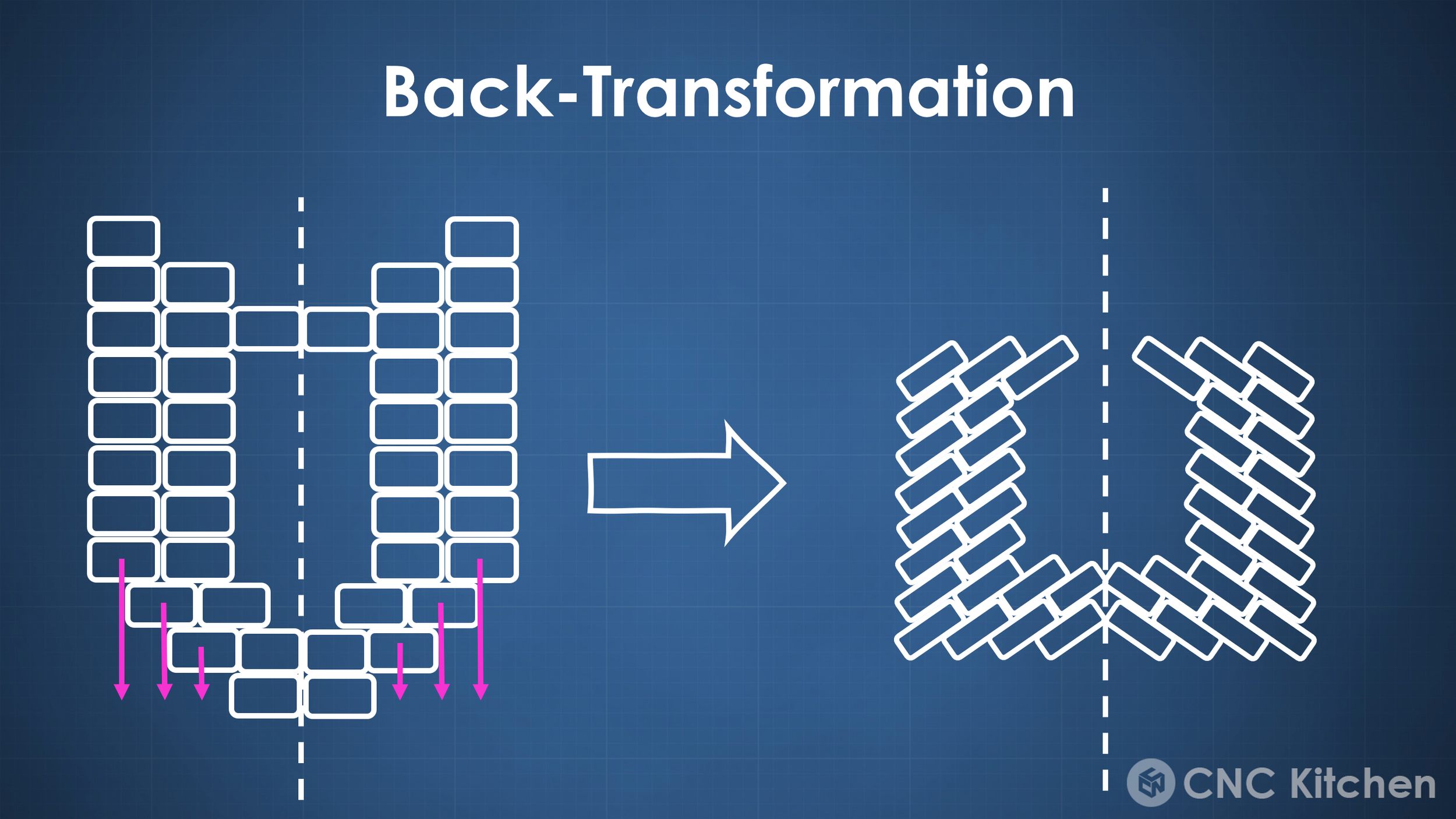
If you want to get into more details on this, I highly recommend taking a closer look at the paper on this method. This leaves you with beautiful non-planar Gcode where print moves are not on one layer, but the part is built up shell by shell. Another great thing about this method is that the layers are now staggered like cinderblocks which might have a positive effect on part strength. What do you think?

Cinderblock-like staggered layers
Conical slicing is quite a simple process if you understand it, and if you had enough clearance around your nozzle, you could even print this Gcode on a regular 3D printer because these are just simple non-planar print moves. I actually want to dig deeper into this conical slicing approach for regular 3-axis printers because there is a slightly modified version of this script available that lets you slice at more shallow angles and might therefore be a great method to print supportless overhangs on even your printer at home without any modifications.

Conical Printing on a regular FDM Printer
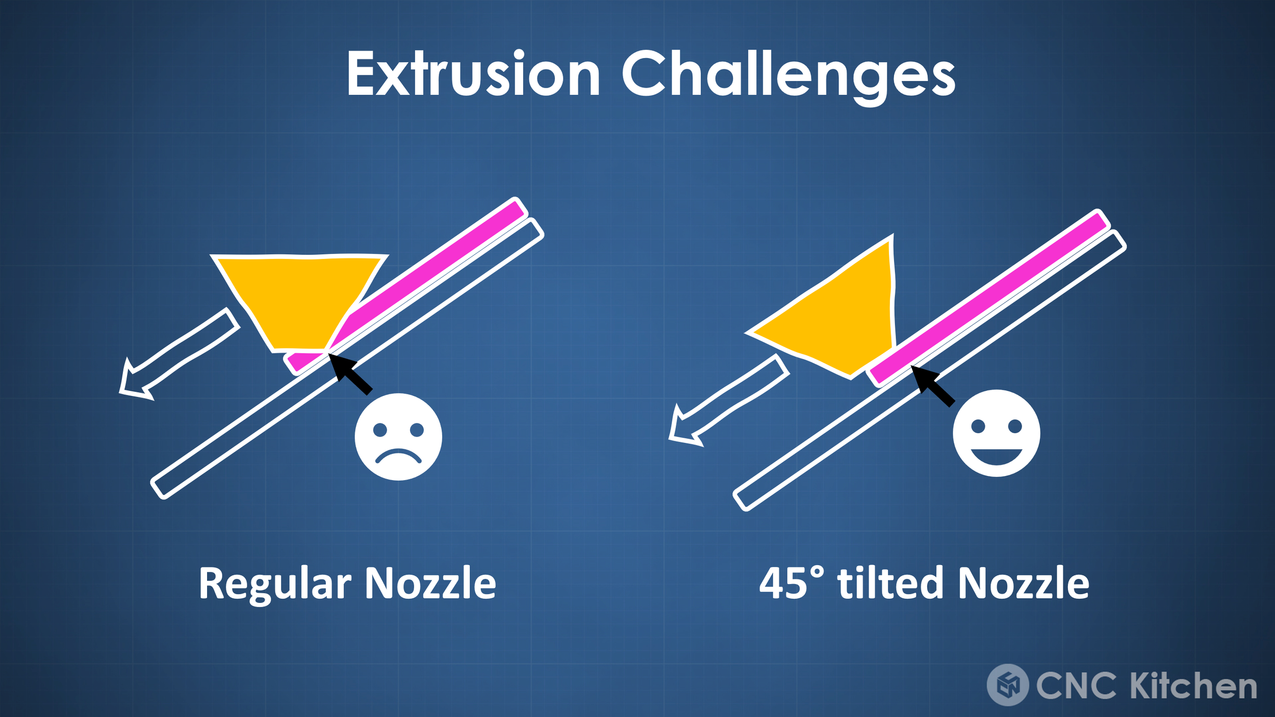
Yet the outstanding feature of RotBot is its 4th axis and the 45° angled nozzle. Even though you can print this conical GCode on a regular printer you’ll quickly run into extrusion problems when the nozzle starts more and more dragging over it’s own extruded material at steeper angles. With the tilted nozzle of the RotBot, you omit this issue becuase you can make sure that you’re always perpendicular to the layer and the extruded line. This additional degree of freedom results in Gcode that doesn’t only reference the X, Y and Z coordinates but also adds a U-value which is the angle of the 4th axis.
All of this leads to these beautiful non-planar print moves where all 4 axes of the printer move at the same time. The prints always start from the center of the conical axis and then slowly grow outwards and upwards. The RotBot can print completely horizontal overhangs without any support material, which opens up quite some opportunities.
Yet, as always, there are also limitations and downsides of a technology, both conical slicing and the RotBot with its 45° angled nozzle. Conical slicing is no slicing approach for every arbitrary geometry. You might have already noticed that all the overhangs you’ve seen so far were facing outwards. Conical slicing suffers from the same problems as cartesian and belt FDM slicing. Print lines can’t start in mid-air, so if you have inward-facing overhangs, you’d still need supports. Another way would be cutting up the part, so that the inward-facing section of the part is sliced with an inward cone instead of an outward cone. This is already implemented, yet it’s currently still a manual process sectioning the parts and stacking the Gcodes ontop of each other to print even more complex parts without the need for support.

Conically Sliced Part with Inward Cone
And this is where we basically are today, at least with this open-source approach. The RotBot and the conical slicing methods are a great demonstration of what can be achievable with relatively simple printer modifications and a super smart, but still simple slicing approach. However, the question remains if we will see this being implemented in commercial machines at some point in the future or if current machines are good enough for most tasks. Seeing the RotBot in person printing parts was a great experience, and I’m sure there would be plenty of applications for it. Yet where I see the even bigger innovation is the conical slicing approach, which can, up to a certain degree, also be used on the conventional printer you might have at home and allow more design freedom and less wasted support structure. The process currently is still very manual with the two python scripts for transforming the STL and back-transforming the G-Code, yet, if you think about it, this was similar to when the first belt printers were developed that actually used a very similar approach for generating their tilted Gcode, yet today we have this directly implemented in branches of CURA and also Raise3D IdeaMaker.
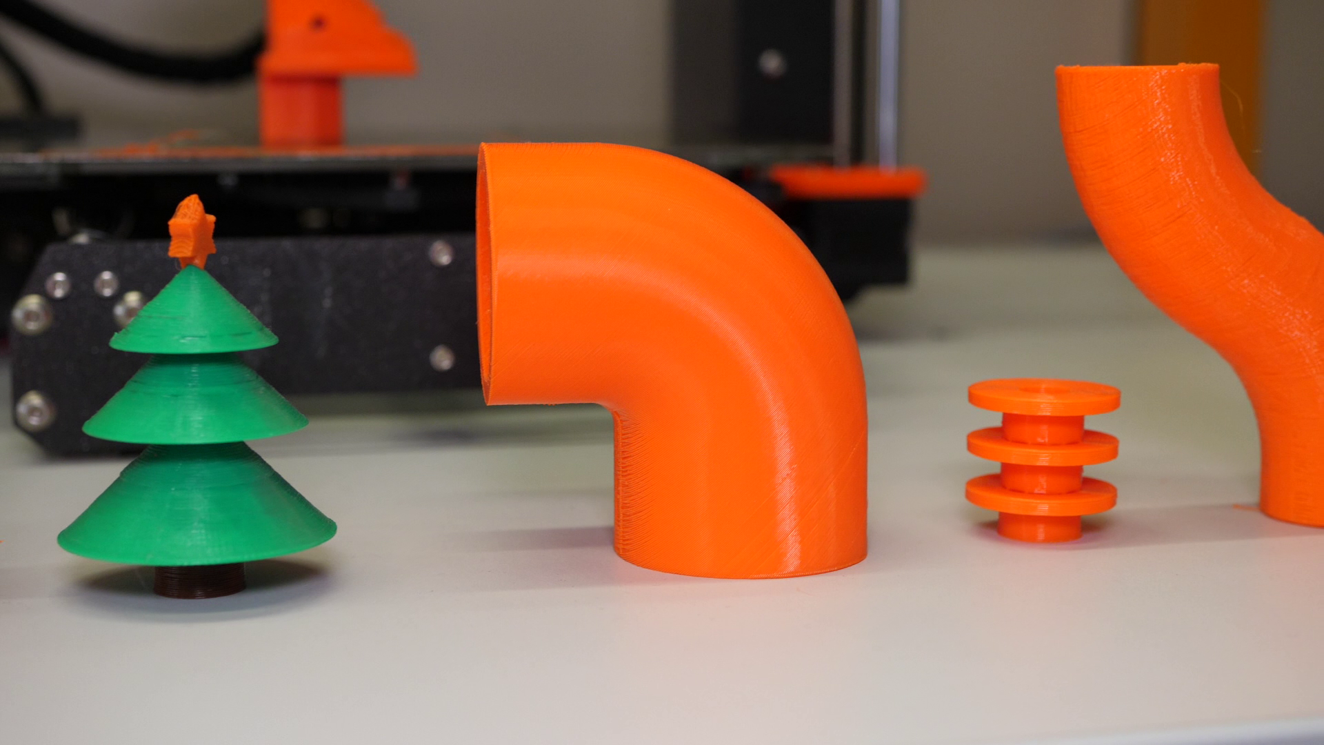
Some conical slicing examples
Conical slicing could be the next big innovation in slicers but will require a ton more work and research, to create algorithms to automatically section parts in areas for conical or just tilted slicing and others that can be printed regularly. If you’re interested in this topic in general, also make sure to check out the work of Rene Mueller on xyzdims.com, where he develops such a universal slicer.

Some of Renes work at XYZdims.com
But what do you think about the 4-axis RotBot and Conical Slicing? Do you only see it in niche applications or would you like to have one or even both available for mainstream machines? Let me know your thoughts down in the YouTube comments!
📚 Further information
RotBot Toolhead Files: https://www.printables.com/model/288723-4-axis-modification-for-mk3s-with-rotational-print
Conical Slicer: https://github.com/RotBotSlicer/Transform
Paper on the RotBot and Conical Slicing: https://www.mdpi.com/2076-3417/11/18/8760
Universal Slicing by Rene Mueller: https://xyzdims.com